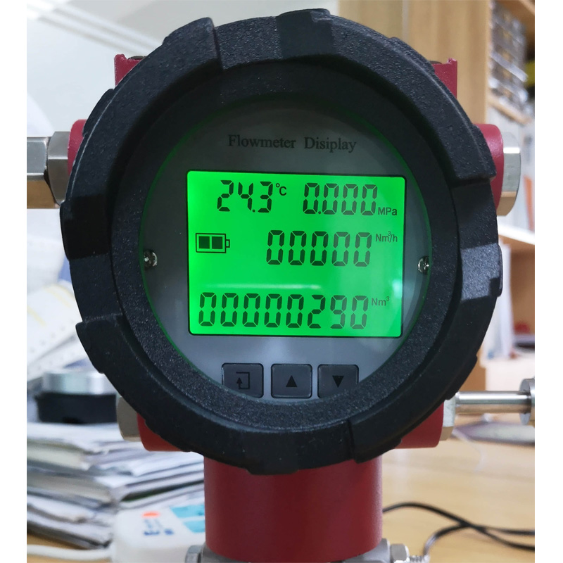
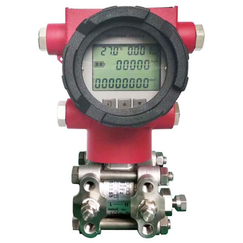
Multivariable DP flow transmitter
Multivariable dp flow transmitter is generally used together with differential pressure flow device such as V-cone, Orifice-plate, Verabar, Nozzle, Venturi etc. to directly display instant flow and total flow. Compared with the traditional differential pressure flow transmitter, multi-Variable differential pressure flow transmitter greatly reduces the cost of installation and after-sales maintenance. Multi-Variable differential pressure flow transmitter is widely used in petroleum, chemical, electric power, metallurgy, shipbuilding, Pharmacy, textile, papermaking and environmental protection industries.
Product Description
Multivariable DP flow transmitter’s Technical data:
- Suitable for all kinds of Differential pressure flow devices
- Turndown ratio: 1 : 100 (standard configuration), 1 : 200(option) , 1 : 400 (option)
- DP sensor accuracy: 0.5%(option), 0.1%(option), 0.2% (standard configuration)
- Operation temperature for DP sensor: -40 ~ 85℃
- Minimum measurable differential pressure range: 10 ~ 1000 Pa.
- Maximum Static pressure rating: 40 Mpa
- Instant flow display range: 0 ~ 99999 m3/h, Cumulative flow display range: 0 ~99999999 m3
- With temperature and pressure compensation, suitable for the gas media with high temperature or steam
- Power supply: 24VDC, 6V lithium battery (option), Solar energy (option)
- Output: 4-20mA (only suitable for 24VDC powered ), corresponding to Instant flow rate; RS485 (only suitable for 24VDC powered ), user can select either 4-20mA or RS485 (Modbus-RTU). It is not available to select both 4 – 20mA and RS485. It is suggested to select RS485 in case the end user wants to read Multiple variables.
- Explosion-proof: Exd II CT4
-
Multivariable DP flow transmitter’s Dimension:
Multivariable DP flow transmitter’s Wiring:
Multivariable DP flow transmitter’s
Output mode
Multivariable DP flow transmitter’s
Wiring
Pulse output
(3-wire)Current output
(4-20mA, 2-wire)RS485 -
Model:
Multivariable DP flow transmitter’s
Model
Multivariable DP flow transmitter’s
Product picture
Remark
Multivariable DP flow transmitter
MDP310-FC1
Without temperature & pressure compensation, be applicable for liquid fluid Multivariable DP flow transmitter
MDP310-FC3
With temperature & pressure compensation, be applicable for gas of Ambient temperature Multivariable DP flow transmitter
MDP310-FC3-V
With temperature & pressure compensation, be applicable for steam
Multivariable dp flow transmitter’s Parameter interface list:
| Interface | Function description |
| K00 | Segment coefficient K00
( Applicable for F ≤ Segment point 1, Segment point 1 = Voltage corresponding to 10% flow rate span ) |
| K01 | Segment coefficient K01
(Applicable for Segment point 1 < F ≤ Segment point 2, Segment point 2 = Voltage corresponding to 17.5% flow rate span ) |
| K02 | Segment coefficient K02
(Applicable for Segment point 2 < F ≤ Segment point 3, Segment point 3 = Voltage corresponding to 25% flow rate span ) |
| K03 | Segment coefficient K03
(Applicable for Segment point 3 < F ≤ Segment point 4, Segment point 4 = Voltage corresponding to 37.5% flow rate span ) |
| K04 | Segment coefficient K04
(Applicable for Segment point 4 < F ≤ Segment point 5, Segment point 5 = Voltage corresponding to 50% flow rate span ) |
| K05 | Segment coefficient K05
(Applicable for Segment point 5 < F ≤ Segment point 6, Segment point 6 = Voltage corresponding to 62.5% flow rate span ) |
| K06 | Segment coefficient K06
(Applicable for Segment point 6 < F ≤ Segment point 7, Segment point 7 = Voltage corresponding to 75% flow rate span ) |
| K07 | Segment coefficient K07
(Applicable for Segment point 7 < F ≤ Segment point 8, Segment point 8 = Voltage corresponding to 87.5% flow rate span ) |
| K08 | Segment coefficient K08
(Applicable for Segment point 8 < F ≤ Voltage corresponding to 100% flow rate span |
| K09 | Instant flow rate unit ( set range: 0, 1, 2, 3 )
0 : m3 (for factory calibration using); 1 : Nm3 (for factory calibration using); 2 : MMSCF /d; 3 : MMSCF /h; |
| K10 | Algorithm selecting ( for manufacturer operating ) |
| K11 | Flow coefficient ( set range: 0 ~ 60000 )
Remark: Manufacturer use special software to calculate the flow coefficient according to the calculation sheet of the throttling elements, then input the calculated flow coefficient in interface K11. |
| K12 | SQRT (square root) ( set range: 0,1, 2, 3, 4 )
0 : No SQRT; 1 : No SQRT x 10; 2 : SQRT; 3 : SQRT x 10; 4 : SQRT x 100 (default) |
| K13 | Differential pressure sensor’s range ( setting range: 0, 1, 2 )
0 : 0 ~ 9.999 Kpa; 1 : 0 ~ 99.99 Kpa; 2 : 0 ~ 999.9 Kpa |
| K14 | Digits of fractional part for instant flow rate ( set range: 0, 1, 2 )
0: No fractional digit; 1: one fractional digit , 2: two fractional digits |
| K15 | Small flow rate cut-off ( set range: 0 ~ 5000 )
Remark: When manufacturer calculating the flow coefficient according to the calculation sheet of the throttling elements, the threshold value of small flow rate cut-off will be automatically calculated, then input the calculated threshold value of small flow rate cut-off at interface K15. |
| K16 | RS485 Communication address ( set range: 1 ~ 255 ) |
| K17 | Baud rate ( set range: 0, 1, 2 )
0: 2400; 1: 4800 , 2: 9600 |
| K18 | Setup instant flow rate corresponding to 20mA ( set range: 0 ~ 60000 )
This parameter interface is only applicable for output:4-20mA |
| K19 | Working mode of transmitter ( set range: 0, 1, 2, 3, 4 )
0 : Display flow rate at the standard condition, time sharing working 1 : Display flow rate at the standard condition, time sharing working and reset 2 : Display flow rate at the standard condition, Real-time working 3 : Display flow rate at the process condition, Real-time working; 4 : Display flow rate at the process condition, time sharing working Remak: Real-time working is applicable for external 24VDC powered, time sharing working is applicable for battery powered. |
| K20 | Temperature test (reserved) |
| K21 | Manually input density compensation ( set range: 0 ~ 600.00 ) |
| K22 | Pressure range’s decimals setting ( set range: 0, 1 ), for manufacturer setting.
0: pressure with 3 decimal places ( Applicable for pressure range ≤10 Mpa); 1: pressure with 2 decimal places ( Applicable for pressure range >10 Mpa) |
| K23 | Operation temperature range selecting ( set range: 0, 1 )
0: -50 ~ 150℃; 1: -50 ~ 450℃ |
| K24 | Current output options ( set range: 0, 1 )
0: For instant flow rate at standard condition; 1: For instant flow rate at the process condition. |
| K25 | Pressure sensor’s range setting (setting range: 0 ~ 60000 ) |
| K26 | Zero point of pressure |
| K27 | Full scale of pressure |
| K28 | Zero point of differential pressure |
| K29 | Full scale of differential pressure |
| K30 | Full scale of output current |
| K31 | Damping time (setting range: 0, 1, 2, 3 ) |
| K32 | Range setting of differential pressure sensor |
| K33 | Accumulative flow adjustment (setting range: 0, 1, 2, 3 )
0: The low 6 digits of accumulative flow at standard condition, positive adjustment; 1: The low 6 digits of accumulative flow at standard condition, negative adjustment; 2: The high 6 digits of accumulative flow at standard condition, positive adjustment; 3: The high 6 digits of accumulative flow at standard condition, negative adjustment. |
| K34 | Adjustment value ( relate to K33 ) |
| K35 | Zero point automatic capture |
| K36 | Automatic cut off the offset of zero point |
| K37 | Instant flow rate setting |
| K38 | Linearity correction setting (setting range: 0, 1, 2 )
0: Without compensation; 1: Differential pressure compensation; 2: Flow rate compensation |
| K39 | Time setting for zero point automatic capture and zero point’s offset cut-off, 3.6 second per unit |
| K40 | Calibration mode setting (setting range: 0, 1 )
0: Normal calibration mode 1: Automatic calibration mode |
| K41 | not use |
| K42 | not use |
| K43 | not use |
| K44 | not use |
| Note: User only need setup parameter at interface K11, K15, parameters at other interfaces have been set up before product leaving factory. | |
Related products
-
In-line type ElectroMagnetic flow meter
HGD Electromagnetic Flow Meter ( New Model: SY-LDY )
Rated 0 out of 5Read more
FAQ
Answer : Please send your question or enquiry to our email: sales@hginstrument.com, we will forward the questions to the related engineer.
Answer : Please communicate with the sales about the return procedure before returning product.
Answer : The delivery time depends on the order quantity and product specification. If the product’s specification is conventional ( not special ), delivery time is 5 or 7 working days for order quantity ≤ 10 pieces; delivery time is 2 or 3 working weeks for order quantity 15 ~ 30 pieces.
Answer : by Courier, by Sea or by Air
Answer : Yes, Generally warranty is one year.
Answer : From year 2015 to year 2021, average annual sales is RMB 350 million ( about USD 54.7 million )


